Draw a Circle Around a Point Using Gcode
Quick G-Code Arc Tutorial: Make G02 & G03 Easy, Avert Mistakes
[ CNCCookbook'southward G-Code Tutorial ]
Circular Interpolation is Motion Forth a Circular Arc
Having but finished discussing linear interpolation, or movement in a straight line, we next come to circular interpolation, which is motion along a circular arc. Other than the adequately exotic ability to follow a "NURBS" path, most g-lawmaking controllers just support two kinds of motion: linear and circular. Round interpolation is quite a bit more demanding on your motorcar as 2 axes have to be precisely coordinated. Drawing a complete circle involves not only coordinated motion but reversal of management at each of the 4 quadrant points. These would be the points corresponding to 0, 90, 180, and 270 degrees. If the machine has any backlash at all, information technology will be obvious at these reversals considering there volition be a glitch in the cut there.
Circular Motility is a Mode Initiated Via G02 and G03
Like linear move (initiated by G00 and G01), circular motion is a mode initiated via G02 or G03. G02 establishes a mode for clockwise round arcs. G03 establishes a mode for counter-clockwise circular arcs.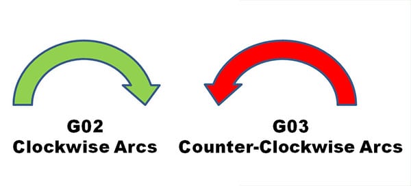
Defining An Arc For the CNC Controller
Once either the G02 or G03 mode is established, arcs are defined in G-Code by identifying their 2 endpoints and the center which must be equi-distant from each endpoint or an alert will occur. The endpoints are easy. The current control point, or location when the block is begun establishes one endpoint. The other may be established past XYZ coordinates. The center is a bit more complex.
Defining the Centre Via IJK Relative Offsets
The center is virtually usually identified by using I, J, or K to constituterelative offsets from the starting point of the arc to the middle. Here is a typical clockwise arc:
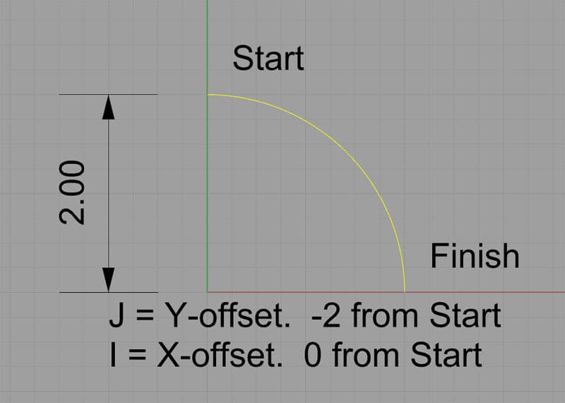
Defining an arc's center with IJK…
This arc starts at X0Y2 and finishes at X2Y0. Information technology'southward heart is at X0Y0. We could specify information technology in k-lawmaking like this:
G02 (Set up the clockwise arc fashion)
X2Y0 I0J-2.0
The I and the J specify relative coordinates from the start indicate to the center. In other words, if we add the I value to the starting indicate'south 10, and the J value to the starting point'south Y, we get the X and Y for the center.
Defining the Eye Via the Radius Using "R"
We tin can also define the middle but by specifying the radius of the circle. In this case, our circle has a radius of 2, so the grand-code might exist simply:
G02
X2Y0 R2
Many of yous will exist deciding right here and now that since R is easier to understand and shorter to write, you're just going to utilize R and forget well-nigh IJK. But, the CNC teachers in the world will suggest that you should adopt IJK. Their statement is that when y'all use IJK, you get a double check that your arc is correct.
Why?
Because the controller gets to compute an actual set of coordinates for the center via IJK. Once information technology has the eye's coordinates, it can check that it is equa-distant from both end points. The cheque of each of those 2 distances is the double bank check. In the example of the "R" format, the controller has no such double check. Information technology has to chose a center that guarantees equal distance.
Personally, I don't know if I agree with the CNC instructors that this is providing whatever extra checking or not. I say go with whichever approach makes sense for your particular state of affairs, but you should definitely be familiar and comfy with both. Y'all're going to need to be comfortable with relative coordinates anyway, as they're darned handy. May likewise get comfortable now.
It's kind of like existence told yous should only utilise the 4-jaw chuck on a lathe when you first start out so you'll get very comfortable dialing it in. It's a good skill to be good at equally a machinist!
Variations in Arc Syntax for Dissimilar One thousand-Code Dialects and Modes
When IJK Are Not Incremental and What About Having Both IJK And R? Plus, Other Modal Shenanigans and Arc Variations
This is some other one of those places where lots of obscure things happen and yous need to know what your controller will do without bold anything. In general, the rule is supposed to be that if you lot have both IJK and R in the same block, R takes precedence and IJK is ignored. Only there are controllers that don't work exactly that way, then be sure you know what's going on.
Thou-Wizard Editor let's you specify several parameters in its Post that decide how arcs piece of work. Hither is a screen shot of the setup options:
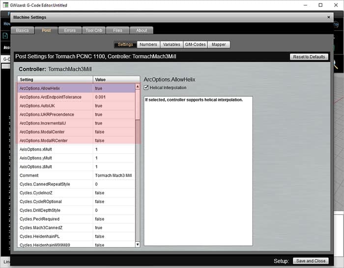
Arc Options for Chiliad-Code Simulation
Allow'south become over these options:
–Incremental vs Accented IJK: We've discussed IJK equally offer coordinates relative to the starting point for the center. Add the I to X, J to Y, and 1000 to Z of the starting betoken and you get the center. Many controls also have the option for IJK to be the absolute coordinates of the center.
–Modal IJK Centers: When IJK are absolute center coordinates, some controllers will remember the final middle defined, hence IJK is modal in that case. When using a control set similar this, yous can only go along issuing XYZ commands for arcs without having to define a new middle each time. It'due south not clear you'll save much though–how often do you lot want to exercise a bunch of arcs with the same center?
–Modal R Centers: Some other variation on the modal center idea is to let the radius defined by "R" to be modal. Any the last R used was, the controller remembers and uses that value again if no R is given. This seems more useful than modal IJK. For case, a pocket might accept arcs for the corners that are all the aforementioned radius.
–Give R Precedence: Equally mentioned, most controllers will utilise "R" when both "R" and "IJK" are given in the same block. But this option allows yous to modify that precedence to IJK if your controller works that way instead.
–Helical Interp.: This option governs whether your controller allows helical interpolation.
The Most Common Trouble Configuring a CAM Post or CNC Simulator: Absolute vs Relative IJK
We've all had the experience of looking at a backplot (or worse, seeing it in the actual tool motion which is pretty scary) and seeing the behemothic almost complete circles and no sign of the familiar part motions we expected to see. Here is a typical example:
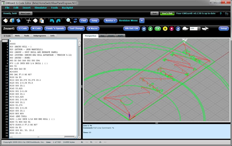
Engrave file with bad Post settings for Arcs…
If you see that sort of thing, the showtime thing to check is absolute versus relative IJK for arcs. The setting has to match between what the CAM produces and what the controller or simulator expects.
Endeavor Our K-Lawmaking Simulator and Editor, Free
Fractions of a Circumvolve, Quadrants, and Controllers
The first matter virtually an arc is it isn't possible to specify more than than a 360 degree arc. At that place are some exceptions to this on some controllers for Helical Interpolation (see below), just considering it tin be useful for helixes. When a full circle is desired, set the offset and stop points equal to one some other:
G01 X3.25 Y2.0
G02 X3.25 Y2.0 I-1.25 J0
Interestingly, y'all can't specify a full circle with the "R" notation. This is because at that place are an space number of circles that start and end at the same indicate of a particular radius, and then the controller has no thought what the correct circle might be.
There is more than funny business still with "R" and larger arcs. For instance, an arc may still be of a particular radius and clockwise (or counter-clockwise direction), simply the eye is ambiguous if yous travel more than than 90 degrees. For example:
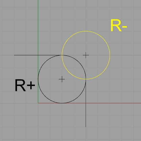
If R is negative, it takes the longer path (in yellowish). Positive gets the shorter path.
Given the two choices shown, the controller chooses the path based on the sign of the radius. Negative forces the longer arc, positive the shorter. The negative sign forces the controller to seek a viable arc of more than 180 degrees.
Some controllers are touchier still and volition not plan an arc that crosses a quadrant line. Hence, the largest angle an arc can follow is ninety degrees, and that bending must not cantankerous 0, ninety, 180, or 270 degrees. For angles of xc degrees that cross a quadrant line, they must be cleaved into 2 pieces, with the join betwixt the pieces being right on the quadrant line.
Full Circles With No XYZ
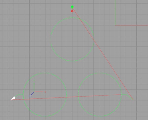
Total circles come about when the start and endpoints are identical and the middle is specified via IJK (think, R leads to an infinite number of circles). Given that you want the beginning and endpoint to exist the aforementioned, you may not need to bother fifty-fifty specifying the end point with XYZ. Some controllers may require it, merely most exercise not. Hither's a simple m-lawmaking program that produces 3 circles in this style:
N45 G0 X-2. Y.75
N46 G1 Z-.5 F10.
N47 Y.5 F30. S2000
N48 G2 J-ane.i
N49 G1 Y.75
N50 Z.2
N51 G0 10.75 Y-three.iv
N52 G1 Z-.5 F10.
N53 Ten.5 F30.
N54 G2 I-ane.1
N55 Ten.75
N56 Z.2
N57 G0 X-4.75 Y-3.4
N58 G1 Z-.five F10.
N59 X-4.five F30.
N60 G2 I1.1
N61 G1 X-four.75
N62 Z.2
And here's what the backplot looks like:
Tip to Make Arc Programming Simpler: Start With Segments
When I'm laying out a toolpath, I adopt to get out the arcs until last. In place of each arc, I but put a line segment whose endpoints correspond to the arc's endpoints. This makes information technology piece of cake to get the rough sketch of the toolpath together apace, and it often seems to make it easier to then become back and convert the lines to arcs in one case the basic structure is already in place.
Helical Interpolation
A helix is an arc that continuously moves in a 3rd dimension, like a screw thread. With helical interpolation, we specify such an arc with G02/G03 in order to movement the cutter along a helix. This tin exist done for thread milling, interpolating a hole, or a variety of other purposes. Here is a backplot from a i/4″ NPT thread manufactory program:
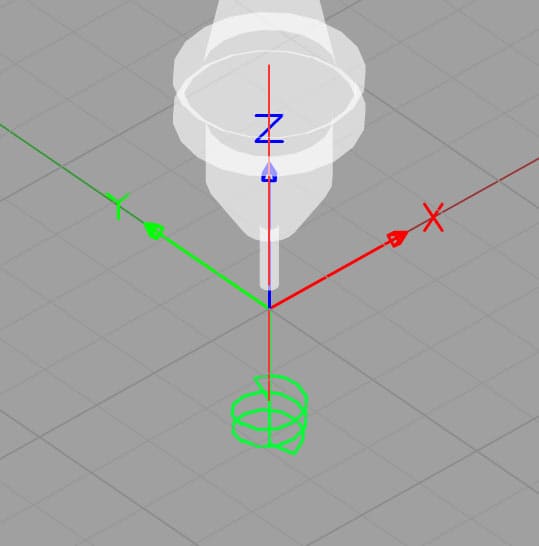
Helix for thread milling…
Here is a sample of the code from the thread milling program:
G01 G91 Z-0.6533 F100.
G01 G42 D08 X0.0235 Y-0.0939 F10.
G03 X0.0939 Y0.0939 Z0.0179 R0.0939
G03 X-0.1179 Y0.1179 Z0.0179 R0.1179
G03 X-0.1185 Y-0.1185 Z0.0179 R0.1185
G03 X0.1191 Y-0.1191 Z0.0179 R0.1191 F16.
G03 X0.1196 Y0.1196 Z0.0179 R0.1196
G03 10-0.1202 Y0.1202 Z0.0179 R0.1202 F26.
G03 Ten-0.1207 Y-0.1207 Z0.0179 R0.1207
G03 X0.1213 Y-0.1213 Z0.0179 R0.1213
G03 X0.1218 Y0.1218 Z0.0179 R0.1218
G03 X-0.0975 Y0.0975 Z0.0179 R0.0975
This is "R" (radius) format for the arcs, and note there is a Z coordinate to specify a depth alter for the end betoken of each arc. This code uses relative motion (G91), so each "Z0.0179″ moves the cutter 0.0179" deeper.
G-Wizard Editor provides some actually useful information to help out with understanding helical interpolation. Here is the Hint from the tertiary line (first arc move):
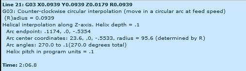
Note the thread pitch here is calculated as 0.1″
GWE will measure and tell y'all the helix pitch, which in this example is 0.100″. That tin can be useful for identifying what sort of thread is being milled. We can also encounter that this particular arc runs from 270 degrees to a scosh more than than nothing (0.1 degrees).
Nosotros'll revisit thread milling in much more detail in a later chapter devoted entirely to the subject. For now, nosotros only wanted you lot to be familiar with the thought that you can brand helixes as well as flat 2 dimensional arcs.
Making Toolpaths Your Machine Volition Be Happier With
Whenever the cutter changes direction, it adds a sure amount of stress. The cutter will bite into the material either more or less than it had been, depending on whether the directions changes towards the workpiece (or uncut material) or away from it. Your machine volition be much happier if you program an arc rather than an sharp straightline change of direction. Fifty-fifty an arc with a very modest radius will let the controller to avoid changing direction instantly, which can leave a marker in the finish in the best example and crusade chatter or other issues in the worst example. For slight changes of direction, it may not exist worth information technology. But the more abrupt the change, with 90 degrees being very abrupt, the greater the likelihood you should use an arc to ease through the turn.
Arcs are also a useful fashion to enter the cutting, rather than having the cutter barge direct in. For information on entering the cut with an arc, see the toolpath page from the Milling Feeds and Speeds Course.
Exercises
one. Dig out your CNC controller transmission and get through the arc settings to set up up GWE to friction match your command's fashion of operating.
2. Do some compose-a-sketch experimentation with GWE. Create some toolpaths that include arcs until y'all're comfortable creating them.
Next Article: Running the GWE G-Code Simulator
Try the Costless Trial Version of G-Wizard One thousand-Code Editor…
Source: https://www.cnccookbook.com/cnc-g-code-arc-circle-g02-g03/
0 Response to "Draw a Circle Around a Point Using Gcode"
Post a Comment